
PETRA II Advanced Industrial Control Trainer – Commissioning & Troubleshooting Guide
This technical reference guide provides systematic diagnostic procedures and corrective actions for setup, commissioning, and operational issues encountered on the PETRA II Advanced Industrial Control Trainer. Use the numbered reference map below to cross-reference physical components with their relevant troubleshooting steps.
Note on Safety & Pneumatic Isolation: Before carrying out any mechanical, pneumatic, or sensor bracket adjustments, ensure the system is safely stopped or the emergency stop circuit is engaged where appropriate. When adjusting cylinder threaded sections or disconnecting pneumatic supply lines, vent trapped air pressure to prevent unintended mechanical movement.
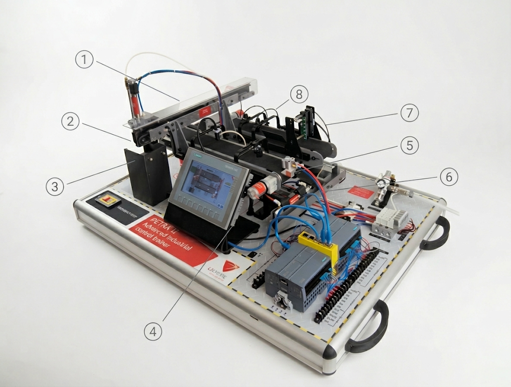
Component Location Index
Refer to your marked reference diagram for the corresponding component callouts:
[1] Gantry: Overhead linear traverse carriage and horizontal drive assembly.
[2] Plunger: Vertical pick-and-place actuator assembly.
[3] Thickness Sensor: Air-jet / pneumatic thickness detection station.
[4] Slot Sensor: Optical detection station configured to detect workpiece slotting.
[5] Part Gripper: Workpiece pick-and-place end-of-arm tooling attached to the transfer arm.
[6] Transfer Arm: Pivoting pneumatic arm mechanism transferring parts between stations.
[7] Hole Sensor: Optical sensing bracket inspecting hole presence.
[8] Cut-Out Sensor: Part profile inspection sensor monitoring edge cut-outs.
At-a-Glance Troubleshooting Matrix
Detailed Calibration & Resolution Procedures
1. Gantry Assembly
Symptom: Plunger gets stuck or catches during horizontal travel
Cause: The gantry travel clearance is restricted by the microswitch striker position.
Procedure: Locate the brass microswitch striker assembly on the gantry carriage. Lower the striker slightly to provide adequate operational clearance throughout the carriage stroke.Symptom: Gantry motor runs continually without stopping at the target position
Cause: The travel limit microswitch is failing to actuate.
Procedure: Raise the brass microswitch striker so that it positively trips the switch lever when reaching each of the 4 stop positions. Verify that the corresponding PLC digital input LED illuminates when actuated.
2. Plunger Actuator
Symptom: Plunger drops but fails to return upward
Cause: The lower limit confirmation signal is missing, or the gantry limit switch is not activated while the plunger cylinder is under load, preventing the control logic from sequencing the return stroke.
Procedure:
Verify whether the brass microswitch plunger striker is physically actuating the switch at full extension. Raise the striker if it is not making firm contact.
If the striker is correctly striking the switch, inspect the magnetic reed/solid-state switch mounted on the plunger cylinder body. Carefully slide the sensor clamp up or down in minute increments until the PLC input registers reliably at full stroke.
3. Thickness Sensor Station
Symptom: Inaccurate part thickness discrimination
Thick parts not detected: Increase the pneumatic supply flow to the sensor via its flow controller / needle valve.
Thin parts detected as thick: Decrease the pneumatic flow to increase switching threshold sensitivity.
Symptom: Workpieces blown off or dislodged from conveyor track
Procedure: The air delivery velocity is set excessively high. Decrease air flow to the thickness sensor considerably until parts remain stable on the track while retaining clean detection.Symptom: Workpieces collide with the sensor body
Procedure: Loosen the knurled thumb screw on the sensor post. Raise the sensor body slightly to clear passing workpieces. Run test parts beneath the sensor, then securely retighten the thumb screw.
4. Slot Sensor
Symptom: Workpiece slot is not detected as parts pass
Procedure: Loosen the bracket locking screw and adjust the vertical optical height until the beam passes directly through the workpiece slot opening. Re-lock and confirm switching on the sensor indicator LED and PLC input table.
5. Part Gripper Adjustment
Correct alignment ensures workpieces seat smoothly within the jaws without binding or jamming against the conveyor:
Gripper Set Too Low (Thick parts will not enter):
Disconnect the pneumatic supply lines from the transfer arm cylinder.
Manually swing and support the transfer arm at approximately 45°.
Loosen the locking/retaining nut located where the transfer arm cylinder rod connects to the transfer arm mounting bracket.
Twist the cylinder shaft counter-clockwise to unscrew the threaded section slightly from the transfer arm, raising the operational jaw height.
Manually lower the arm to the conveyor to check fitment with thick workpieces. Repeat fine adjustments until parts slide into the gripper freely.
Tighten the retaining nut firmly and reconnect the pneumatic lines.
Gripper Set Too High (Parts pass beneath or fail to enter):
Follow the procedure above to isolate and position the arm.
Thread the cylinder rod shaft clockwise into the transfer arm attachment bracket to lower the working height.
Confirm clearance and engagement, tighten the lock nut, and restore pneumatic connections.
6. Transfer Arm
Symptom: Arm does not raise or lower during automatic sequence
Cause: The controller has not verified that the arm reached its previous home or extended position, halting the sequential state machine.
Procedure: Inspect the magnetic position sensors mounted on the cylinder barrel. Manually position the arm at its travel limits and adjust the sensor positions along the cylinder tie-rod/slot until the onboard sensor LED and PLC status input register reliably.
7. Hole Sensor Station
Symptom: Parts fail to enter hole sensor and fall off the conveyor track
Cause: The transfer arm delivery limit stop is incorrectly positioned, causing the arm to deposit parts off-centre.
Procedure: Loosen the locking retaining nut on the nylon limit stop screw. Adjust the nylon screw depth until the transfer arm deposits the workpiece squarely in line with the conveyor guide rails. Manually test part transition, then securely lock the retaining nut.Symptom: Parts collide with the hole sensor mounting bracket
Procedure: Loosen the Allen socket cap screws on both sides of the sensor mounting bracket. Realign the bracket position along the guide rail to provide adequate side clearance, and retighten both screws evenly.Symptom: All parts detected as having no holes
Procedure: Loosen sensor retaining screws and adjust height so that the sensors for H2 and H4 can be clearly seen through the holes in the test pieces. Retighten and test that the PLC inputs are correct when the test pieces are passed through.
8. Cut-Out Sensor
Symptom: Edge cut-out profile not detected
Procedure: Adjust the mounting height of the optical cut-out sensor to align with the vertical height of the part's cut-out feature. Verify output switching on the sensor status LED during manual part transit.